Monday, October 27, 2008
transparent proxy
pas cari referensi seting proxy dapet artikel yang ini ni..
..................................................................................................................................................................................................
by Vivek Gite
My Setup:
i) System: HP dual Xeon CPU system with 8 GB RAM (good for squid).
ii) Eth0: IP:192.168.1.1
iii) Eth1: IP: 192.168.2.1 (192.168.2.0/24 network (around 150 windows XP systems))
iv) OS: Red Hat Enterprise Linux 4.0 (Following instruction should work with Debian and all other Linux distros)
Eth0 connected to internet and eth1 connected to local lan i.e. system act as router.
Server Configuration
• Step #1 : Squid configuration so that it will act as a transparent proxy
• Step #2 : Iptables configuration
o a) Configure system as router
o b) Forward all http requests to 3128 (DNAT)
• Step #3: Run scripts and start squid service
First, Squid server installed (use up2date squid) and configured by adding following directives to file:
# vi /etc/squid/squid.conf
Modify or add following squid directives:
-------------------------------------------------------------------------------------------------------------------------------------
httpd_accel_host virtual
httpd_accel_port 80
httpd_accel_with_proxy on
httpd_accel_uses_host_header on
acl lan src 192.168.1.1 192.168.2.0/24
http_access allow localhost
http_access allow lan
-------------------------------------------------------------------------------------------------------------------------------------
Where,
• httpd_accel_host virtual: Squid as an httpd accelerator
• httpd_accel_port 80: 80 is port you want to act as a proxy
• httpd_accel_with_proxy on: Squid act as both a local httpd accelerator and as a proxy.
• httpd_accel_uses_host_header on: Header is turned on which is the hostname from the URL.
• acl lan src 192.168.1.1 192.168.2.0/24: Access control list, only allow LAN computers to use squid
• http_access allow localhost: Squid access to LAN and localhost ACL only
• http_access allow lan: -- same as above --
Here is the complete listing of squid.conf for your reference (grep will remove all comments and sed will remove all empty lines, thanks to David Klein for quick hint ):
# grep -v "^#" /etc/squid/squid.conf | sed -e '/^$/d'
OR, try out sed (thanks to kotnik for small sed trick)
# cat /etc/squid/squid.conf | sed '/ *#/d; /^ *$/d'
_____________________________________________________________________________________
Output:
hierarchy_stoplist cgi-bin ?
acl QUERY urlpath_regex cgi-bin \?
no_cache deny QUERY
hosts_file /etc/hosts
refresh_pattern ^ftp: 1440 20% 10080
refresh_pattern ^gopher: 1440 0% 1440
refresh_pattern . 0 20% 4320
acl all src 0.0.0.0/0.0.0.0
acl manager proto cache_object
acl localhost src 127.0.0.1/255.255.255.255
acl to_localhost dst 127.0.0.0/8
acl purge method PURGE
acl CONNECT method CONNECT
cache_mem 1024 MB
http_access allow manager localhost
http_access deny manager
http_access allow purge localhost
http_access deny purge
http_access deny !Safe_ports
http_access deny CONNECT !SSL_ports
acl lan src 192.168.1.1 192.168.2.0/24
http_access allow localhost
http_access allow lan
http_access deny all
http_reply_access allow all
icp_access allow all
visible_hostname myclient.hostname.com
httpd_accel_host virtual
httpd_accel_port 80
httpd_accel_with_proxy on
httpd_accel_uses_host_header on
coredump_dir /var/spool/squid
______________________________________________________________________________________________________________________
Iptables configuration
Next, I had added following rules to forward all http requests (coming to port 80) to the Squid server port 3128 :
iptables -t nat -A PREROUTING -i eth1 -p tcp --dport 80 -j DNAT --to 192.168.1.1:3128
iptables -t nat -A PREROUTING -i eth0 -p tcp --dport 80 -j REDIRECT --to-port 3128
Here is complete shell script. Script first configure Linux system as router and forwards all http request to port 3128 (Download the fw.proxy shell script):
_________________________________________________________________________________________
#!/bin/sh
# squid server IP
SQUID_SERVER="192.168.1.1"
# Interface connected to Internet
INTERNET="eth0"
# Interface connected to LAN
LAN_IN="eth1"
# Squid port
SQUID_PORT="3128"
# DO NOT MODIFY BELOW
# Clean old firewall
iptables -F
iptables -X
iptables -t nat -F
iptables -t nat -X
iptables -t mangle -F
iptables -t mangle -X
# Load IPTABLES modules for NAT and IP conntrack support
modprobe ip_conntrack
modprobe ip_conntrack_ftp
# For win xp ftp client
#modprobe ip_nat_ftp
echo 1 > /proc/sys/net/ipv4/ip_forward
# Setting default filter policy
iptables -P INPUT DROP
iptables -P OUTPUT ACCEPT
# Unlimited access to loop back
iptables -A INPUT -i lo -j ACCEPT
iptables -A OUTPUT -o lo -j ACCEPT
# Allow UDP, DNS and Passive FTP
iptables -A INPUT -i $INTERNET -m state --state ESTABLISHED,RELATED -j ACCEPT
# set this system as a router for Rest of LAN
iptables --table nat --append POSTROUTING --out-interface $INTERNET -j MASQUERADE
iptables --append FORWARD --in-interface $LAN_IN -j ACCEPT
# unlimited access to LAN
iptables -A INPUT -i $LAN_IN -j ACCEPT
iptables -A OUTPUT -o $LAN_IN -j ACCEPT
# DNAT port 80 request comming from LAN systems to squid 3128 ($SQUID_PORT) aka transparent proxy
iptables -t nat -A PREROUTING -i $LAN_IN -p tcp --dport 80 -j DNAT --to $SQUID_SERVER:$SQUID_PORT
# if it is same system
iptables -t nat -A PREROUTING -i $INTERNET -p tcp --dport 80 -j REDIRECT --to-port $SQUID_PORT
# DROP everything and Log it
iptables -A INPUT -j LOG
iptables -A INPUT -j DROP
__________________________________________________________________________________________
Save shell script. Execute script so that system will act as a router and forward the ports:
# chmod +x /etc/fw.proxy
# /etc/fw.proxy
# service iptables save
# chkconfig iptables on
Start or Restart the squid:
# /etc/init.d/squid restart
# chkconfig squid on
Desktop / Client computer configuration
Point all desktop clients to your eth1 IP address (192.168.2.1) as Router/Gateway (use DHCP to distribute this information). You do not have to setup up individual browsers to work with proxies.
How do I test my squid proxy is working correctly?
See access log file /var/log/squid/access.log:
# tail -f /var/log/squid/access.log
Above command will monitor all incoming request and log them to /var/log/squid/access_log file. Now if somebody accessing a website through browser, squid will log information.
Problems and solutions
(a) Windows XP FTP Client
All Desktop client FTP session request ended with an error:
Illegal PORT command.
I had loaded the ip_nat_ftp kernel module. Just type the following command press Enter and voila!
# modprobe ip_nat_ftp
Please note that modprobe command is already added to a shell script (above).
(b) Port 443 redirection
I had block out all connection request from our router settings except for our proxy (192.168.1.1) server. So all ports including 443 (https/ssl) request denied. You cannot redirect port 443, from debian mailing list, "Long answer: SSL is specifically designed to prevent "man in the middle" attacks, and setting up squid in such a way would be the same as such a "man in the middle" attack. You might be able to successfully achive this, but not without breaking the encryption and certification that is the point behind SSL".
Therefore, I had quickly reopen port 443 (router firewall) for all my LAN computers and problem was solved.
(c) Squid Proxy authentication in a transparent mode
You cannot use Squid authentication with a transparently intercepting proxy.
moga2 bermanfaat..... thanx uncle google
Thursday, October 23, 2008
Tuesday, October 21, 2008
How do you use extended traceroute?
Author: David Davis
Just as you can use the extended ping command to determine what kind of connectivity problems you’re having, you can use the extended traceroute command to narrow down where the problem is happening. The basic traceroute command tests for the same thing as ping, but its benefit is that it lists the routers at each hop of the route to the destination. Extended traceroute goes much further, allowing you to tweak how it works.
Just as you can use the extended ping command to determine what kind of connectivity problems you’re having, you can use the extended traceroute command to narrow down where the problem is happening. The basic traceroute command tests for the same thing as ping, but its benefit is that it lists the routers at each hop of the route to the destination. Extended traceroute goes much further, allowing you to tweak how it works.
Here is an example:
Router# traceroute 1.1.1.1
Source address: 2.2.2.2
Numeric display [n]:
Timeout in seconds [4]:
Probe count [3]:
Minimum Time to Live [1]:
Maximum Time to Live [30]:
Port Number [33434]:
Loose, Strict, Record, Timestamp, Verbose[none]:
Type escape sequence to abort.
Tracing the route to 1.1.1.1
1 3.3.3.1 16 msec 16 msec 16 msec
2 3.3.3.2 28 msec 28 msec 32 msec
3 2.2.2.2 32 msec 28 msec *
For more information on extended route, please see Cisco’s documentation “Using the Extended Ping and Extended Traceroute Commands.”
For more information on these commands, also see my TechRepublic article “Implement Regular Monitoring and Improve Cisco Router Performance.”
Use extended ping and extended traceroute to better troubleshoot your Cisco network
Author: David Davis
The ping command is just about as simple as it gets when it comes to troubleshooting. It asks, “Are you there?” and waits for a response. However, there is a lot more to ping if you use the Cisco IOS extended version.
There are a lot of assumptions and default settings in the standard version of ping. Extended ping allows you, the network admin, to see and determine every option that you want to specify for your ping test. For example, here are some of the many options that you can specify with extended ping:
- Protocols: While 99 percent of the time you will use IP, most admins don’t know that you can do an AppleTalk, CLNS, Novell, or other types of ping with extended ping.
- Repeat count: How many pings do you want to send? The default is five with standard ping, but you could send 999 with extended ping. Perhaps your network is having trouble periodically — you could test this with extended ping.
- Datagram size: While the default is to send a 100-byte ping, with extended ping you could send very large ping packets. Perhaps your network is having trouble with large data transfers.
- Timeout: The default timeout is two seconds, but you could allow ping to wait much longer for a reply if you choose to do so.
- Source interface: I think this is very important — you can specify the source of your ping because, otherwise, the receiving router may not be able to see all interfaces of your router and your standard ping may fail.
- Loose, Strict, Record, Timestamp, Verbose: You can specify these options to gain additional information about your ping tests, such as forcing the ping to take a strict path through the network.
Here is an example of an extended ping:
Router# ping
Protocol [ip]:
Target IP address: 1.1.1.1
Repeat count [5]: 10
Datagram size [100]:
Timeout in seconds [2]:
Extended commands [n]: y
Source address or interface: 2.2.2.2
Type of service [0]:
Set DF bit in IP header? [no]:
Validate reply data? [no]:
Data pattern [0xABCD]:
Loose, Strict, Record, Timestamp, Verbose[none]:
Sweep range of sizes [n]:
Type escape sequence to abort.
Sending 5, 100-byte ICMP Echos to 2.2.2.2, timeout is 2 seconds:
!!!!!!!!!!
Success rate is 100 percent (10/10), round-trip min/avg/max = 20/98/157 ms
Router#
You can actually perform an extended ping, all on the command line, like this:
ping ip 1.1.1.1 data 0000 repeat 500 size 18000 verbose
Also, to break out of an extended ping or traceroute, you can press [Ctrl]+[Shift]6.
For more information on the extended ping command, please see the Cisco documentation “Using the Extended Ping and Extended Traceroute Commands.”
Analyze network traffic with tcpdump
Tcpdump may not have a slick frontend like other packet analyzers such as Wireshark and Ettercap, but this command line tool makes up for its lack of fancy graphics with power and flexibility. In this IT Dojo video, Bill Detwiler shows you why tcpdump is great tool for network debugging and security monitoring.
Once you’ve watched this IT Dojo video, you can find a link to the original TechRepublic article and print the tip from tech republic IT Dojo Blog.
Speaker: Bill Detwiler
http://video.techrepublic.com.com/2422-14075_11-237041.html
Monday, October 20, 2008
Install Zimbra Email Server
Before You Begin
Make sure that you have a fresh, clean installation of Ubuntu 6.06 LTS (Server) prepared on the computer you are planning to run Zimbra. You can follow our HowTo: Install Ubuntu 6.06 LTS (Server) in order to prepare your server installation.
You will also need to install a few extra packages not included in the default installation.
sudo apt-get update
sudo apt-get -y install perl libidn11 curl fetchmail libpcre3 libgmp3c2 libexpat1 libxml2 openssl
Configuring the Hostname
While this step is not required, I strongly recommend that you make an entry in your hosts file to allow for easy DNS resolution of the host name. To make this change you need to open the "/etc/hosts" file with a text editor and add an entry for your hostname.
sudo pico /etc/hosts
127.0.0.1 localhost
127.0.1.1 hostname.domain.tld hostname mail.yourdomain.com
Then simply save and exit ("Ctrl + X").
Setting up DNS
Before your server will be useful you will need to make some DNS changes to the domain name you're going to configure. Zimbra can manage domain for multiple domain names, but external mail servers need a pointer in order to know which server handles mail for the given domain. In our example we will be configuring the server to handle mail for "users@yourdomain.com". Given this information we will need to make sure there is an MX record set up for "yourdomain.com" in DNS that points to the server's IP address.
The MX record you'll want to configure for "yourdomain.com" is as follows:
@ MX 5 mail.yourdomain.com
You'll also want to set up an "A" record for the "mail" host on "yourdomain.com" that points to your external IP address.
mail A 215.38.22.122
At GoDaddy.com you simply log into your account. Then go to edit the domain name of your choice. Once in edit mode click the "Total DNS Control" option (you'll have to scroll down and look on the left). In the DNS manager you can now add an MX record for the "@" host that points to your external IP address. If all of this sounds foreign to you then check the HowTo's on how to set up a web server using Ubuntu 6.06 LTS Server for more information on how to forward ports, configure DNS, and set up daemons.
Download and Install
After you have prepared your server install you'll need to download the Zimbra email suite. The download link is as follows:
Download URL: http://www.zimbra.com/community/downloads.html
You can also use the following to start the installation:
sudo wget --continue -O /tmp/zcs.UBUNTU6.tgz \
http://easynews.dl.sourceforge.net/sourceforge/zimbra/zcs-4.5.2_GA_699.UBUNTU6.tgz
cd /usr/local/src
sudo tar -zxf /tmp/zcs.UBUNTU6.tgz
cd ./zcs
sudo ./install.sh
You'll be asked several questions during the install. Here is a list:
#> Press Return to continue
#> Install zimbra-ldap [Y] yes
#> Install zimbra-logger [Y] yes
#> Install zimbra-mta [Y] yes
#> Install zimbra-snmp [Y] yes
#> Install zimbra-store [Y] yes
#> Install zimbra-spell [Y] yes
#> The system has been modified. Continue? [N] yes
Depending on your network configuration you may be asked if you want to change your hostname.
#> DNS ERROR resolving hostname.domain.tld
#> It is suggested that the hostname be resolveable via DNS
#> Change hostname [Yes] yes
#> Please enter the logical hostname for this host [hostname.domain.tld] mail.yourdomain.com
#> DNS ERROR resolving MX for mail.yourdomain.com
#> It is suggested that the domain name have an MX record configured in DNS
#> Change domain name? [Yes] no
The "MX" record it is asking you for is so that other email servers know where to send mail destined for "user@mail.yourdomain.com". Since we're configuring this to be "user@yourdomain.com" there is no need for an MX record on the mail.yourdomain.com hostname. NOTE: You MUST add/update the MX record on "yourdomain.com" in order to receive mail.
Configuration
At this point you need to set a few values in order to have the server start up correctly. The only one that is required to be set is the Administrator's password. This can be set by choosing option "6" from the main menu and then option "4" from the "zimbra-store" menu.
#> Password for admin@mail.yourdomain.com (min 6 characters): [dXGV_DAI] administrator
Type "r" to return to the main menu.
Once you have the configuration complete message showing you can type "a" to apply the settings.
#> *** CONFIGURATION COMPLETE - press 'a' to apply
#> Select from menu, or press 'a' to apply config (? - help) a
#> Save configuration data to a file? [Yes] yes
#> Save config in file: [/opt/zimbra/config.10720] /opt/zimbra/config.saved.default
#> The system will be modified - continue? [No] yes
#> Notify Zimbra of your installation? [Yes] no
If everything went right then you can now access your administration screen at https://mail.yourdomain.com:7071
You'll want to note the "https" instead of the "http". You may also need to change the "mail.yourdomain.com" to the IP address of the server on which you installed zimbra.http://www.linuxatschool.com/index.php?page=43
Postfix Mail Server Configuration
Postfix, designed by Wietse Venema, is a mail server built with security in mind and specifically designed to replace Sendmail. The project began development in a security sensitive atmosphere. This secure focus has had a major advantage over a product like Sendmail that was created in a non-hostile environment and then had to be adapted to protect users form the evils of the common day. Postfix simplicity and focus on security are both major reasons why it is selected over Sendmail. This tutorial will show you how to configure a basic Postfix Mail server for CentOS,OpenSuse and Ubuntu.
Related Postfix Training
Postfix Configuration
Postfix Mail Server Design
Control SPAM with Postfix
Postfix Mailbox Changes
Postfix Mail Gateway
Postfix Mail Server Course
1.Change the MTA
The default MTA may be Sendmail or another MTA that has been already set up. In order to make sure that Postfix is the default you can use the alternatives program with Centos or uninstall Sendmail.
To select an alternative from those MTAs available use this command:
alternatives --config mta
You will see this output which will allow you to choose an MTA using a number.
alternatives --config mta
There are 2 programs which provide 'mta'.
Selection Command
-----------------------------------------------
* 1 /usr/sbin/sendmail.sendmail
+ 2 /usr/sbin/sendmail.postfix
Enter to keep the current selection[+], or type selection number:
2. Configure the Hostname in the smtpd Banner
When your mail server connects to another mail server to transfer messages it performs a HELO which sends it's hostname to the other server. This is one of the reasons your hostname is so important. In fact, many servers in order to verify the integrity of mail exchanges will do a DNS lookup to verify the FQDN (Fully Qualified Domain Name) matches what if provided in the HELO. If they do not match some servers will not allow the transfer of mail. Therefore, make sure your FQDN is what is present in the HELO.
myhostname
Postfix requires a fully qualified domain name or FQDN. A FQDN includes the hostname of the server as well as the domain name like this:
mail.example.com
This includes the hostname “mail” and the domain name “example.com”.
The command hostname will give you the hostname for the server. It is important that this be a canonical name, in other words if the server hostname is mail and the domain is bigstrike.org the canonical hostname would be mail.bigstrike.org.
To find the hostname of the server type this command:
hostnameTo change the hostname of the server add the hostname after the command:
hostname mail.example.comHostname is important for Postfix because it uses a parameter myhostname which in turn determines a parameter mydomain. These are two necessary parameters for starting Postfix.
Creating a Fully Qualified Domain Name
Postfix provides a utility that enables you to change the hostname into a FQDN. Use the command postconf with the -e option for editing Here is an example:
postconf -e myhostname=mail.bigstrike.org
Setting myhostname is important because a Fully Qualified Domain Name will also change the setting for mydomain. If your FQDN is mail.example.com then the parameter form mydomain is automatically example.com.
3. Edit /etc/postfix/main.cf
First, make a backup of your files located in the /etc/postfix directory. This will provide a reference of changes you have made as well as give you a rescue file so you can start over after a mistake. Now edit the myhostname parameter to provide the FQDN.
myhostname = mail.example.com
Postfix is smart enough to understand that the domain listed in myhostname is the domain for the server. You can also set the mydomain parameter.
mydomain = example.com
Set your inet_interfaces to all.
inet_interfaces = all
4. Configure Relays
Postfix will not allow any relaying of mail for any domains by default. It will relay mail for the localhost but all other relays must be explicitly set. In the initial configuration for a one domain server, this setting for allowing your domain to relay mail is found in the mydestination parameter.
mydestination = $mydomain
If you would like to also accept mail for your hostname you may also add this information to the configuration.
mydestination = $mydomain, $myhostname
If you have created CNAMEs in your DNS settings for your domain that would also need to be added here. A CNAME (Canonical Name) is like an alias, www for example. If you want to accept mail for these they must be entered as well. If they do not fit on one line you can enter a new one on each line with a space in front of them as Postfix will not recognize them without a space.
mydestination =
$mydomain,
$myhostname,
www.$mydomain,
tech.$mydomain
Each line ends with a comma and starts with a space.
5 .Configure Outgoing Domain
The outgoing domain parameter provides a way to verify where mail came from. This parameter setting will be used by Postfix whenever mail is sent for an address that is not fully qualified. Again,this setting is located in the main.cf file.
myorigin = $mydomain
This parameter is a way for Postfix to set a domain name when the user sends an email and no domain name is specified in the envelope or header address. The default value of myorigin is the value of myhostname, again another reason myhostname is important to set up.
Here is how this all works. If the myhostname is:
mail.example.com
And if the user who sends mail is mike, then the resulting mail return address is: mike@mail.example.commike@mail.example.com
username@myhostname(FQDN)
If users do not want the hostname of the server in the return address then set the myorigin to this parameter:
myorigin = $mydomain
Now using the example above the return address for the user mike will be:
mike@example.commike@example.com
username@domain
The last example is usually what people like.
6. Changes Necessary for Network Connections
Just like Sendmail, Postfix will not accept connections from other computers until you take a few steps to enable it. There are several lines that must be uncommented and then your configuration placed in it. The example will assume that your domain is bigstrike.org and the FQDM is mail.bigstrike.org. Be sure to put in the correct network for your settings.
mydomain = example.com
myorigin = $mydomain
myhostname = mail.example.com
mydestination = $myhostname, localhost, localhost.$mydomain
mynetworks = 192.168.3.0/24
inet_interfaces = all
Now restart Postfix.
service postfix restart
or
/etc/init.d/postfix restart
7. root Mail Configuration
Postfix has a focus on security, especially when it comes to running programs as root. As a result, Postfix will deliver mail to root locally but it will not allow other programs to run as root. This means that programs like procmail cannot be used to deliver mail to the root user. Therefore you will need to create an alias for the root user so that mail that is intended for root will be delivered to a non-privileged user.
Edit /etc/aliases and create a line like this:
root: mike
Whatever user you choose make sure that it is an account that is on the system. Do not use the admin account as it is tied to other things on the system.
Once you have added the username run the command:
newaliases
8. Testing the Current Configuration
It is important to test Postfix in stages so that you can confirm you current work before you go further.
Verify that Postfix is running:
/etc/init.d/postfix start
/etc/init.d/postfix stop
/etc/init.d/postfix reload
Now send a test message to root. Note the sendmail binary is provided by Postfix as a way to make migration from Sendmail to Postfix easier.
For Centos use this command:
# echo test | /usr/sbin/sendmail -f root root
tail -f /var/log/maillog
For Suse and Ubuntu use this command:
# echo test | /usr/sbin/sendmail -f root root
tail /var/log/mail.log
When you view the log file, you should see similar information to this. Remember, in the example the user who will receive root mail is mike, be sure you check the user that you create.
Feb 17 18:29:21 mail sendmail[17437]: m1I2TLAf017437: from=root, size=5, class=0, nrcpts=1, msgid=< 200802180229.m1I2TLAf017437@mail.example.com200802180229.m1I2TLAf017437@mail.example.com>, relay=root@localhost
Feb 17 18:29:21 mail postfix/smtpd[17438]: connect from mail.example.com[127.0.0.1]
Feb 17 18:29:21 mail postfix/smtpd[17438]: A11F7724374: client=mail.example.com[127.0.0.1]
Feb 17 18:29:21 mail postfix/cleanup[17441]: A11F7724374: message-id=< 200802180229.m1I2TLAf017437@mail.example.com200802180229.m1I2TLAf017437@mail.example.com>
Feb 17 18:29:21 mail postfix/qmgr[17433]: A11F7724374: from=< root@mail.example.comroot@mail.example.com>, size=504, nrcpt=1 (queue active)
Feb 17 18:29:21 mail sendmail[17437]: m1I2TLAf017437: to=root, ctladdr=root (0/0), delay=00:00:00, xdelay=00:00:00, mailer=relay, pri=30005, relay=[127.0.0.1] [127.0.0.1], dsn=2.0.0, stat=Sent (Ok: queued as A11F7724374)
Feb 17 18:29:21 mail postfix/smtpd[17438]: disconnect from mail.example.com[127.0.0.1]
Feb 17 18:29:21 mail postfix/local[17442]: A11F7724374: to=< mike@example.commike@example.com>, orig_to=< root@mail.example.comroot@mail.example.com>, relay=local, delay=0.06, delays=0.05/0/0/0, dsn=2.0.0, status=sent (delivered to mailbox)
Feb 17 18:29:21 mail postfix/qmgr[17433]: A11F7724374: removed
This shows the process of how the mail moves from one module of postfix to the next.
If you do this command you should see your mail:
less /var/mail/mike
From root@mail.example.comroot@mail.example.com Sun Feb 17 18:29:21 2008
Return-Path: < root@mail.example.comroot@mail.example.com>
X-Original-To: root@mail.example.comroot@mail.example.com
Delivered-To: root@mail.example.comroot@mail.example.com
Received: from mail.example.com (mail.example.com [127.0.0.1])
by mail.example.com (Postfix) with ESMTP id A11F7724374
for < root@mail.example.comroot@mail.example.com>; Sun, 17 Feb 2008 18:29:21 -0800 (PST)
Received: (from root@localhost)
by mail.example.com (8.13.8/8.13.8/Submit) id m1I2TLAf017437
for root; Sun, 17 Feb 2008 18:29:21 -0800
Date: Sun, 17 Feb 2008 18:29:21 -0800
From: root < root@mail.example.comroot@mail.example.com>
Message-Id: < 200802180229.m1I2TLAf017437@mail.example.com200802180229.m1I2TLAf017437@mail.example.com>
To: undisclosed-recipients:;
test
There it is a working Postfix.
You may also want to test from a telnet session. First, install telnet if it is not installed:
Centos Command:
yum install telnet
Ubuntu Command:
sudo apt-get install telnet
Use the commands in blue, be sure to place a “.” on a line by itself after your message. So it should look like this:
This is a test email from telnet.
.
Note the “.” is on a line by itself.
# telnet localhost 25
or
# telnet mail.example.com 25
Trying 127.0.0.1...
Connected to mail.example.com.
Escape character is '^]'.
220 mail.example.com ESMTP Postfix
HELO mike.example.com
250 mail.example.com
MAIL FROM: < root@example.comroot@example.com>
250 Ok
RCPT TO:
250 Ok
DATA
354 End data with
This is a test mail from telnet.
.
250 Ok: queued as 276E1794BF1
QUIT
221 Bye
Connection closed by foreign host.
Now check the mail for mike (or whatever user).
less /var/mail/mike
From root.example.com@example.comroot.example.com@example.com Sun Feb 17 18:42:49 2008
Return-Path: < root.example.com@example.comroot.example.com@example.com>
X-Original-To: mike@example.commike@example.com
Delivered-To: mike@example.commike@example.com
Received: from root.example.com (mail.example.com [127.0.0.1])
by mail.example.com (Postfix) with SMTP id 1B4BB724372
for < mike@example.commike@example.com>; Sun, 17 Feb 2008 18:41:15 -0800 (PST)
Message-Id: < 20080218024135.1B4BB724372@mail.example.com20080218024135.1B4BB724372@mail.example.com>
Date: Sun, 17 Feb 2008 18:41:15 -0800 (PST)
From: root.example.com@example.comroot.example.com@example.com
To: undisclosed-recipients:;
This is a test mail from telnet.
Now mail has been confirmed working two different ways.
http://beginlinux.com/index.php/server_training/mail-server/1041-postfix-mail-server-set-up
Friday, October 17, 2008
Setting up MikroTik RouterOS™
Downloading and Installing the MikroTik RouterOS™
The download and installation process of the MikroTik RouterOS™ is described in the following diagram: 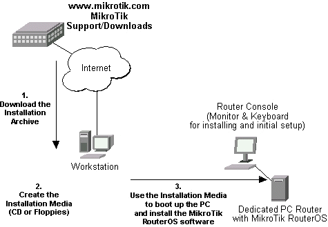
1. Download the basic installation archive file.
Depending on the desired media to be used for installing the MikroTik RouterOS™ please chose one of the following archive types for downloading:- ISO image of the installation CD, if you have a CD writer for creating CDs. The ISO image is in the MTcdimage_v2-7-x_dd-mmm-yyyy.zip archive file containing a bootable CD image. The CD will be used for booting up the dedicated PC and installing the MikroTik RouterOS™ on its hard-drive or flash-drive.
- MikroTik Disk Maker, if you want to create 3.5" installation floppies. The Disk Maker is a self-extracting archive DiskMaker_v2-7-x_dd-mmm-yyyy.exe file, which should be run on your Windows 95/98/NT4/2K/XP workstation to create the installation floppies. The installation floppies will be used for booting up the dedicated PC and installing the MikroTik RouterOS™ on its hard-drive or flash-drive.
- Netinstall, if you want to install RouterOS™ over a LAN with one floppy boot disk, or alternatively using PXE-boot option supported by some network interface cards, that allows truly networked installation. Netinstall program works on Windows 95/98/NT4/2K/XP.
2. Create the installation media
Use the appropriate installation archive to create the Installation CD or floppies.- For the CD, write the ISO image onto a blank CD.
- For the floppies, run the Disk Maker on your Windows workstation to create the installation floppies. Follow the instructions and insert the floppies in your FDD as requested, label them as Disk 1,2,3, etc.
3. Install the MikroTik RouterOS™ software.
Your dedicated PC router hardware should have:- An advanced 4th generation (core frequency 100MHz or more), 5th generation (Intel Pentium, Cyrix 6X86, AMD K5 or comparable) or newer Intel IA-32 (i386) compatible motherboard and processor (uniprocessor only, dual processors and other SMP configurations are not supported);
- from 32MB to 1GB RAM (from 48MB suggested);
- 30MB or more PRIMARY MASTER IDE HDD or IDE flashdrive.
- A network adapter (NE2000 compatible PCI or ISA Ethernet card, or any other supported NIC, see the supported device list on our web page);
- A SECONDARY MASTER CD drive set as primary boot device, if you want to use the created CD for installing the MikroTik RouterOS™ onto the primary master HDD;
- A 3.5" FDD set as primary boot device, if you want to use the created set of floppies for installing the MikroTik RouterOS™;
- A monitor and keyboard for installation and initial setup of the MikroTik Router. The monitor and keyboard do not need to be connected to the router after it is set up for connecting to it over the network.
After successful installation please remove the installation media from your CD or floppy disk drive and hit 'Enter' to reboot the router. While the router will be starting up for the first time you will be given a Software ID for your installation and asked to supply a valid software license key (Software Key) for it. Write down the Software ID. You will need it to obtain the Software License through the MikroTik Account Server. If you need extra time to obtain the Software License Key, you may want to power off the router. Type shutdown in the Software key prompt and power the router off when the router is halted.
Notes
The installation from CD or network requires Base (paid) License. If you intend to obtain the Free Demo License, you should use the floppy installation media.The hard disk will be entirely reformatted during the installation and all data on it will be lost!
You can move the hard drive with MikroTik RouterOS™ installed to a new hardware without loosing a license, but you cannot move the RouterOS™ to a different hard drive without purchasing an another license (except hardware failure situations). For additional information write to support[at]mikrotik.com
Obtaining the Software License
The MikroTik RouterOS™ Software licensing process is described in the following diagram: 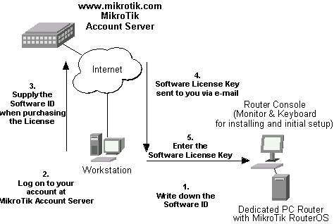
After installing the router and starting it up for the first time you will be given a Software ID.
- Write down the Software ID reported by the RouterOS™.
- If you have an account with MikroTik, follow to the next step.
If you do not have an account at www.mikrotik.com, just press the 'New' button on the upper right-hand corner of the MikroTik's web page to create your account.
You will be presented with the Account Sign-Up Form where you chose your account name and fill in the required information.
- To obtain the Software License Key, log on to your account at www.mikrotik.com entering your account name and password (upper right-hand corner on this webpage), for example:

- After logging on to the Account Server select "Free Demo License" or "Order Software License" in the Account Menu.
- The Software Key will be sent to the email address, which has been specified in your account setup.
- Read your email and enter the Software Key at the router's console, for example:
Software ID: 5T4V-IUT
Software key: 4N7X-UZ8-6SP
After entering the correct Software License Key you will be presented with the MikroTik Router's login prompt.
Notes
The CD or Netinstall installation cannot be 'unlocked' with the Free Demo Key. Use the Floppy installation or purchase a Licensed Key.Logging into the MikroTik Router
When logging into the router via terminal console, you will be presented with the MikroTik RouterOS™ login prompt. Use 'admin' and no password (hit 'Enter') for logging on to the router for the first time, for example:
MikroTik v2.7
Login: admin
Password:
The password can be changed with the /password command.
Adding Software Packages
The basic installation comes with only the "system" package and few other packages. This includes basic IP routing and router administration. To have additional features such as IP Telephony, OSPF, wireless and so on, you will need to download additional software packages.The additional software packages should have the same version as the system package. If not, the package won't be installed. Please consult the MikroTik RouterOS™ Software Package Installation and Upgrading Manual for more detailed information about installing additional software packages.
Software Licensing Issues
If you want to upgrade your 'free' version of MikroTik RouterOS™ installation to a 'paid' version, please purchase the new Software License KEY for the Software ID you used when getting the 'free' demo license. Similarly, if additional license is required to enable the functionality of a software package, the license should be obtained for the Software ID of your system. The new key should be entered using the /system license set key command, and the router should be rebooted afterwards:
[admin@MikroTik] ip firewall src-nat> /system license print
      software-id: "SB6T-R8T"
              key: "3YIV-ZW8-DH2"
 upgradable-unitl: apr/01/2004
[admin@MikroTik] system license> feature print
Flags: X - disabled
#   FEATURE
0 X AP
1 X synchronous
2 X radiolan
3 X wireless-2.4gHz
4   licensed
[admin@MikroTik] system license> set key=D46G-IJ6-QW3
[admin@MikroTik] system license>/system reboot
Reboot, yes? [y/N]: y
system will reboot shortly
Notes
If there is no appropriate license, the appropriate interfaces wont show up under the interface list, even though the packages can be installed on the MikroTik RouterOS™ and corresponding drivers loaded.Navigating the Terminal Console
Welcome Screen and Command Prompt
After logging into the router you will be presented with the MikroTik RouterOS™ Welcome Screen and command prompt, for example:
  MMM      MMM       KKK                          TTTTTTTTTTT      KKK
MMMM    MMMM       KKK                          TTTTTTTTTTT      KKK
MMM MMMM MMM  III  KKK  KKK  RRRRRR     OOOOOO      TTT     III  KKK  KKK
MMM  MM  MMM  III  KKKKK     RRR  RRR  OOO  OOO     TTT     III  KKKKK
MMM      MMM  III  KKK KKK   RRRRRR    OOO  OOO     TTT     III  KKK KKK
MMM      MMM  III  KKK  KKK  RRR  RRR   OOOOOO      TTT     III  KKK  KKK

MikroTik RouterOS v2.7 (c) 1999-2003       http://www.mikrotik.com/

Terminal xterm detected, using multiline mode
[admin@MikroTik] >
The command prompt shows the identity name of the router and the current menu level, for example:
[admin@MikroTik] >                Base level menu
[admin@MikroTik] interface>       Interface configuration
[admin@MikroTik] ip address>      IP Address management
Commands
The list of available commands at any menu level can be obtained by entering the question mark '?', for example:[admin@MikroTik] > ?
driver Driver management
file Local router file storage.
import Run exported configuration script
interface Interface configuration
log System logs
password Change password
ping Send ICMP Echo packets
port Serial ports
quit Quit console
radius Radius client settings
redo Redo previosly undone action
setup Do basic setup of system
snmp SNMP settings
undo Undo previous action
user User management
ppp Point to Point Protocol
ip IP options
queue Bandwidth management
system System information and utilities
tool Diagnostics tools
routing Various routing protocol settings
export Print or save an export script that can be used to restore
configuration
[admin@MikroTik] > ip ?
accounting Traffic accounting
address Address management
arp ARP entries management
dns DNS settings
firewall Firewall management
neighbor Neighbors
packing Packet packing settings
pool IP address pools
route Route management
service IP services
policy-routing Policy routing
upnp
dhcp-client DHCP client settings
dhcp-server DHCP server settings
dns-cache DNS cache management
ipsec IP security
export Print or save an export script that can be used to restore
configuration
[admin@MikroTik] > ip
The list of available commands and menus has short descriptions next to the items. You can move to the desired menu level by typing its name and hitting the [Enter] key, for example:
[admin@MikroTik] >                      Base level menu
[admin@MikroTik] > driver               Enter 'driver' to move to the driver level
                                    menu
[admin@MikroTik] driver> /             Enter '/' to move to the base level menu
                                    from any level
[admin@MikroTik] > interface            Enter 'interface' to move to the interface
                                    level menu
[admin@MikroTik] interface> /ip        Enter '/ip' to move to the IP level menu
                                    from any level
[admin@MikroTik] ip>
A command or an argument does not need to be completed, if it is not ambiguous. For example, instead of typing 'interface' you can type just 'in' or 'int'. To complete a command use the [Tab] key.
The commands may be invoked from the menu level, where they are located, by typing its name. If the command is in a different menu level than the current one, then the command should be invoked using its full (absolute) or relative path, for example:
[admin@MikroTik] ip route> print                  Prints the routing table
[admin@MikroTik] ip route> .. address print       Prints the IP address table
[admin@MikroTik] ip route> /ip address print      Prints the IP address table
The commands may have arguments. The arguments have their names and values. Some commands, may have a required argument that has no name.
Summary on executing the commands and moving between the menu levels
       Command                               Action
command [Enter]      Execute the command
[?]                  Show the list of all available commands
command [?]          Display help on the command and the list of arguments
command argument [?] Display help on the command's argument
[Tab]                Complete the command/word. If the input is ambiguous, a
                  second [Tab] gives possible options
/                    Move up to the base level
/command             Execute the base level command
..                   Move up one level
""                   Enter an empty string
"word1 word2"        Enter 2 words that contain a space
You can abbreviate names of levels, commands and arguments.
For the IP address configuration, instead of using the 'address' and 'netmask' arguments, in most cases you can specify the address together with the number of true bits in the network mask, i.e., there is no need to specify the 'netmask' separately. Thus, the following two entries would be equivalent:
/ip address add address 10.0.0.1/24 interface ether1
/ip address add address 10.0.0.1 netmask 255.255.255.0 interface ether1
Notes
You must specify the size of the network mask in the address argument, even if it is the 32-bit subnet, i.e., use 10.0.0.1/32 for address 10.0.0.1 and netmask 255.255.255.255Accessing the Router Remotely Using Web Browser and WinBox Console
Summary
The MikroTik router can also be accessed remotely using http and WinBox Console, for example, using the web browser of your workstation.Description
The Winbox Console is used for accessing the MikroTik Router configuration and management features using graphical user interface.All Winbox interface functions are as close as possible to Console functions: all Winbox functions are exactly in the same place in Terminal Console and vice versa (except functions that are not implemented in Winbox). That is why there are no Winbox sections in the manual.
The Winbox Console plugin loader, the winbox.exe program, can be retrieved from the MikroTik router, the URL is http://router_address/winbox/winbox.exe Use any web browser on Windows 95/98/ME/NT4.0/2000/XP to retrieve the router's web page with the mentioned link.
Note that if you change the default port for www service on the router, you will have to specify it just after the IP address separated by column (eg. 10.0.0.1:8080).
The winbox plugins are cached on the local disk for each MikroTik RouterOS™ version. The plugins are not downloaded, if they are in the cache, and the router has not been upgraded since the last time it has been accessed.
Starting the Winbox Console
When connecting to the MikroTik router via http (TCP port 80 by default), the router's Welcome Page is displayed in the web browser, for example: 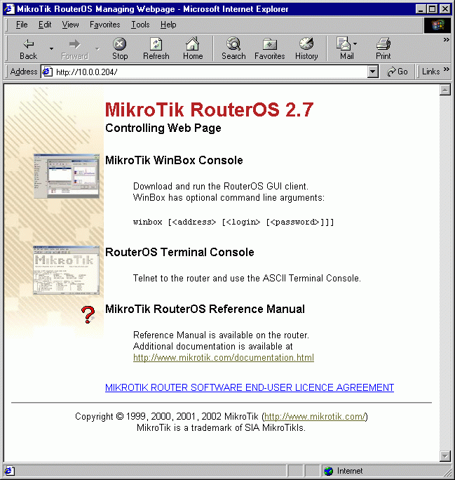
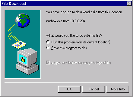
By clicking on the Winbox Console link you can start the winbox.exe download. Choose the option "Run this program from its current location" and click "OK":
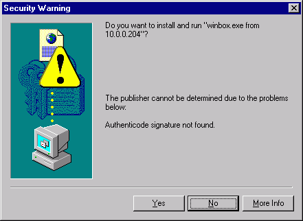
Accept the security warning, if any:
Alternatively, you can save the winbox.exe program to your disk and run it from there.
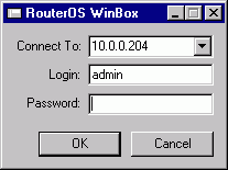
The winbox.exe program opens the Winbox login window. Login to the router by specifying the IP address (and the port number if you have changed it from the default value of 80), user name, and password, for example:
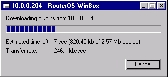
Watch the download process of Winbox plugins:
The Winbox console is opened after the plugins have been downloaded:
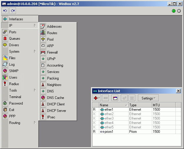
The Winbox Console uses TCP port 3986 (not secure) or 3987 (secure; requires security package to be installed). After logging on to the router you can work with the MikroTik router's configuration through the Winbox console and perform the same tasks as using the regular console.
Overview of Common Functions
You can use the menu bar to navigate through the router's configuration menus, open configuration windows. By double clicking on some list items in the windows you can open configuration windows for the specific items, and so on.
There are some hints for using the Winbox Console:
- To open the required window, simply click on the corresponding menu item.
- To add a new entry you should click on the
 icon in the corresponding window.
 - To remove an existing entry click on the
 icon.
icon. - To enable an item, click on the
 icon.
icon. - To disable an item, click on the
 icon.
icon. - To make or edit a comment for a selected item, click on the
 icon.
icon. - To refresh a window, click on the
 icon.
icon. - To undo an action, click on the
 icon above the main menu.
 - To redo an action, click on the
 icon above the main menu.
 - To logout from the Winbox Console, click on the
 icon.
icon.
Troubleshooting for Winbox Console
- I cannot open the Winbox Console
- Check the port and address for www service in /ip service print list. Make sure the address you are connecting from matches the network you've specified in address field and that you've specified the correct port in the Winbox loader. The command /ip service set www port=80 address=0.0.0.0/0 will change these values to the default ones so you will be able to connect specifying just the correct address of the router in the address field of Winbox loader
- The Winbox Console uses TCP port 3986 (not secure) or 3987 (secure; requires security package to be installed). Make sure you have access to it through the firewall.
Configuring Basic Functions
Working with Interfaces
Before configuring the IP addresses and routes please check the /interface menu to see the list of available interfaces. If you have Plug-and-Play cards installed in the router, it is most likely that the device drivers have been loaded for them automatically, and the relevant interfaces appear on the /interface print list, for example:
[admin@MikroTik] interface> print
Flags: X - disabled, D - dynamic, R - running
#    NAME                 TYPE             MTU
0  R ether1               ether            1500
1  R ether2               ether            1500
2  R ether3               ether            1500
3  R ether4               ether            1500
4  R ether5               ether            1500
5  R sync1                sync             1500
6  R pc1                  pc               1500
7  R ether6               ether            1500
8  R prism1               prism            1500
[admin@MikroTik] interface>
The interfaces need to be enabled, if you want to use them for communications. Use the /interface enable name command to enable the interface with a given name or number, for example:
[admin@MikroTik] interface> print
Flags: X - disabled, D - dynamic, R - running
#   NAME                 TYPE             MTU
0 X  ether1               ether            1500
0 X  ether2               ether            1500
[admin@MikroTik] interface> enable 0
[admin@MikroTik] interface> enable ether2
[admin@MikroTik] interface> print
Flags: X - disabled, D - dynamic, R - running
#   NAME                 MTU   TYPE
0  R ether1               ether            1500
0  R ether2               ether            1500
[admin@MikroTik] interface>
The interface name can be changed to a more descriptive one by using the /interface set command:
[admin@MikroTik] interface> set 0 name=Public
[admin@MikroTik] interface> set 1 name=Local
[admin@MikroTik] interface> print
Flags: X - disabled, D - dynamic, R - running
#   NAME                 MTU   TYPE
0  R Public               ether            1500
0  R Local                ether            1500
[admin@MikroTik] interface>
Use of the 'setup' Command
The initial setup of the router can be done by using the /setup command which enables an interface, assigns an address/netmask to it, and configures the default route. If you do not use the setup command, or need to modify/add the settings for addresses and routes, please follow the steps described below.Notes
The device drivers for NE2000 compatible ISA cards need to be loaded using the add command under the /drivers menu. For example, to load the driver for a card with IO address 0x280 and IRQ 5, it is enough to issue the command:
[admin@MikroTik] driver> add name=ne2k-isa io=0x280
[admin@MikroTik] driver> print
Flags: I - invalid, D - dynamic
#   DRIVER                                IRQ IO       MEMORY   ISDN-PROTOCOL
0 D RealTek 8139
1 D Intel EtherExpressPro
2 D PCI NE2000
3   ISA NE2000                            280
4   Moxa C101 Synchronous                              C8000
[admin@MikroTik] driver>
There are some other drivers that should be added manually. Please refer to the respective manual sections for the detailed information on how drivers are to be loaded. Adding Addresses
Assume you need to configure the MikroTik router for the following network setup: 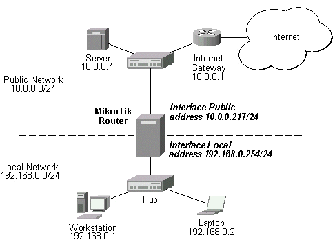
In the current example we use two networks:
- The local LAN with network address 192.168.0.0 and 24-bit netmask 255.255.255.0 The router's address is 192.168.0.254 in this network.
- The ISP's network with address 10.0.0.0 and 24-bit netmask 255.255.255.0 The router's address is 10.0.0.217 in this network.
[admin@MikroTik] ip address> add address 10.0.0.217/24 interface Public
[admin@MikroTik] ip address> add address 192.168.0.254/24 interface Local
[admin@MikroTik] ip address> print
Flags: X - disabled, I - invalid, D - dynamic
#   ADDRESS            NETWORK         BROADCAST       INTERFACE
0   10.0.0.217/24      10.0.0.217      10.0.0.255      Public
1   192.168.0.254/24   192.168.0.0     192.168.0.255   Local
[admin@MikroTik] ip address>
Here, the network mask has been specified in the value of the address argument. Alternatively, the argument 'netmask' could have been used with the value '255.255.255.0'. The network and broadcast addresses were not specified in the input since they could be calculated automatically.
Notes
Please note that the addresses assigned to different interfaces of the router should belong to different networks.Configuring the Default Route
You can see two dynamic (D) and connected (C) routes, which have been added automatically when the addresses were added in the example above:
[admin@MikroTik] ip route> print
Flags: X - disabled, I - invalid, D - dynamic, J - rejected,
C - connect, S - static, R - rip, O - ospf, B - bgp
 #    DST-ADDRESS        G GATEWAY         DISTANCE INTERFACE
 0 DC 192.168.0.0/24     r 0.0.0.0         0        Local
 1 DC 10.0.0.0/24        r 0.0.0.0         0        Public
[admin@MikroTik] ip route> print detail
Flags: X - disabled, I - invalid, D - dynamic, J - rejected,
C - connect, S - static, R - rip, O - ospf, B - bgp
 0 DC dst-address=192.168.0.0/24 preferred-source=192.168.0.254
      gateway=0.0.0.0 gateway-state=reachable distance=0 interface=Local

 1 DC dst-address=10.0.0.0/24 preferred-source=10.0.0.217 gateway=0.0.0.0
      gateway-state=reachable distance=0 interface=Public

[admin@MikroTik] ip route>
These routes show, that IP packets with destination to 10.0.0.0/24 would be sent through the interface Public, whereas IP packets with destination to 192.168.0.0/24 would be sent through the interface Local. However, you need to specify where the router should forward packets, which have destination other than networks connected directly to the router.
Example
In the following example the default route (destination 0.0.0.0, netmask 0.0.0.0) will be added. In this case it is the ISP's gateway 10.0.0.1, which can be reached through the interface Public:
[admin@MikroTik] ip route> add gateway=10.0.0.1
[admin@MikroTik] ip route> print
Flags: X - disabled, I - invalid, D - dynamic, J - rejected,
C - connect, S - static, R - rip, O - ospf, B - bgp
 #    DST-ADDRESS        G GATEWAY         DISTANCE INTERFACE
 0  S 0.0.0.0/0          r 10.0.0.1        1        Public
 1 DC 192.168.0.0/24     r 0.0.0.0         0        Local
 2 DC 10.0.0.0/24        r 0.0.0.0         0        Public
[admin@MikroTik] ip route>
Here, the default route is listed under #0. As we see, the gateway 10.0.0.1 can be reached through the interface 'Public'. If the gateway was specified incorrectly, the value for the argument 'interface' would be unknown.
Notes
You cannot add two routes to the same destination, i.e., destination-address/netmask! It applies to the default routes as well. Instead, you can enter multiple gateways for one destination. For more information on IP routes, please read the relevant topic in the Manual.If you have added an unwanted static route accidentally, use the remove command to delete the unneeded one. You will not be able to delete dynamic (DC) routes. They are added automatically and represent routes to the networks the router connected directly.
Testing the Network Connectivity
From now on, the /ping command can be used to test the network connectivity on both interfaces. You can reach any host on both connected networks from the router.Example
In the example below it's seen, hows does ping command work:
[admin@MikroTik] ip route> /ping 10.0.0.4
10.0.0.4 64 byte ping: ttl=255 time=7 ms
10.0.0.4 64 byte ping: ttl=255 time=5 ms
10.0.0.4 64 byte ping: ttl=255 time=5 ms
3 packets transmitted, 3 packets received, 0% packet loss
round-trip min/avg/max = 5/5.6/7 ms
[admin@MikroTik] ip route>
[admin@MikroTik] ip route> /ping 192.168.0.1
192.168.0.1 64 byte ping: ttl=255 time=1 ms
192.168.0.1 64 byte ping: ttl=255 time=1 ms
192.168.0.1 64 byte ping: ttl=255 time=1 ms
3 packets transmitted, 3 packets received, 0% packet loss
round-trip min/avg/max = 1/1.0/1 ms
[admin@MikroTik] ip route>
The workstation and the laptop can reach (ping) the router at its local address 192.168.0.254, If the router's address 192.168.0.254 is specified as the default gateway in the TCP/IP configuration of both the workstation and the laptop, then you should be able to ping the router:
C:\>ping 192.168.0.254
Reply from 192.168.0.254: bytes=32 time=10ms TTL=253
Reply from 192.168.0.254: bytes=32 time<10ms ttl="253" bytes="32" ttl="253">ping 10.0.0.217
Reply from 10.0.0.217: bytes=32 time=10ms TTL=253
Reply from 10.0.0.217: bytes=32 time<10ms ttl="253" bytes="32" ttl="253">ping 10.0.0.4
Request timed out.
Request timed out.
Request timed out.

C:\>
Notes
You cannot access anything beyond the router (network 10.0.0.0/24 and the Internet), unless you do the one of the following:- Use source network address translation (masquerading) on the MikroTik router to 'hide' your private LAN 192.168.0.0/24 (see the information below), or
- Add a static route on the ISP's gateway 10.0.0.1, which specifies the host 10.0.0.217 as the gateway to network 192.168.0.0/24. Then all hosts on the ISP's network, including the server, will be able to communicate with the hosts on the LAN.
To set up routing, it is required that you have some knowledge of configuring TCP/IP networks. There is a comprehensive list of IP resources compiled by Uri Raz at http://www.private.org.il/tcpip_rl.html We strongly recommend that you obtain more knowledge, if you have difficulties configuring your network setups.
Application Examples
Next will be discussed situation with 'hiding' the private LAN 192.168.0.0/24 'behind' one address 10.0.0.217 given to you by the ISP.Application Example with Masquerading
If you want to 'hide' the private LAN 192.168.0.0/24 'behind' one address 10.0.0.217 given to you by the ISP, you should use the source network address translation (masquerading) feature of the MikroTik router. Masquerading is useful, if you want to access the ISP's network and the Internet appearing as all requests coming from the host 10.0.0.217 of the ISP's network. The masquerading will change the source IP address and port of the packets originated from the network 192.168.0.0/24 to the address 10.0.0.217 of the router when the packet is routed through it.Masquerading conserves the number of global IP addresses required and it lets the whole network use a single IP address in its communication with the world.
To use masquerading, a source NAT rule with action 'masquerade' should be added to the firewall configuration:
[admin@MikroTik] ip firewall src-nat> add action=masquerade out-interface=Public
[admin@MikroTik] ip firewall src-nat> print
Flags: X - disabled, I - invalid, D - dynamic
0   src-address=0.0.0.0/0:0-65535 dst-address=0.0.0.0/0:0-65535
   out-interface=Public protocol=all icmp-options=any:any flow=""
   connection="" content="" limit-count=0 limit-burst=0 limit-time=0s
   action=masquerade to-src-address=0.0.0.0 to-src-port=0-65535

[admin@MikroTik] ip firewall src-nat>
Notes
Please consult the Firewall Manual for more information on masquerading.Application Example with Bandwidth Management
Mikrotik RouterOS™ V2.7 offers extensive queue management.Assume you want to limit the bandwidth to 128kbps on downloads and 64kbps on uploads for all hosts on the LAN. Bandwidth limitation is done by applying queues for outgoing interfaces regarding the traffic flow. It is enough to add two queues at the MikroTik router:
[admin@MikroTik] queue simple> add interface=Local max-limit=128000
[admin@MikroTik] queue simple> add interface=Public max-limit=64000
[admin@MikroTik] queue simple> print
Flags: X - disabled, I - invalid, D - dynamic
0   name="queue1" src-address=0.0.0.0/0 dst-address=0.0.0.0/0
   interface=Local limit-at=0 queue=default priority=8 max-limit=128000

1   name="queue2" src-address=0.0.0.0/0 dst-address=0.0.0.0/0
   interface=Public limit-at=0 queue=default priority=8 max-limit=64000

[admin@MikroTik] queue simple>
Leave all other parameters as set by default. The limit is approximately 128kbps going to the LAN (download) and 64kbps leaving the client's LAN (upload).
Notes
The queues have been added for the outgoing interfaces regarding the traffic flow.Please consult the Queues Manual for more information on bandwidth management and queuing.
Application Example with NAT
Assume we have moved the server in our previous examples from the public network to our local one: 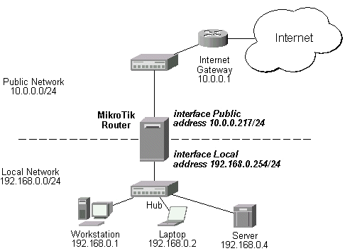
The server'would have been s address now is 192.168.0.4, and we are running web server on it that listens to the TCP port 80. We want to make it accessible from the Internet at address:port 10.0.0.217:80. This can be done by means of Static Network Address translation (NAT) at the MikroTik Router. The Public address:port 10.0.0.217:80 will be translated to the Local address:port 192.168.0.4:80. One destination NAT rule is required for translating the destination address and port:
[admin@MikroTik] ip firewall dst-nat> add action=nat protocol=tcp \
dst-address=10.0.0.217/32:80 to-dst-address=192.168.0.4
[admin@MikroTik] ip firewall dst-nat> print
Flags: X - disabled, I - invalid, D - dynamic
0   src-address=0.0.0.0/0:0-65535 in-interface=all
   dst-address=10.1.0.217/32:80 protocol=tcp icmp-options=any:any flow=""
   src-mac-address=00:00:00:00:00:00 limit-count=0 limit-burst=0
   limit-time=0s action=nat to-dst-address=192.168.0.4 to-dst-port=0-65535

[admin@MikroTik] ip firewall dst-nat>
http://www.mikrotik.com/documentation/manual_2.7/Basic/Basic.html
Subscribe to:
Comments (Atom)